

TECHNICAL WORK
Applied numerical modelling and engineering.
Selected examples of numerical modelling, seabed assessment and engineering calculation workflows applied to offshore design challenges.
POCO HYDRO · ORIGINAL REGIONAL MODEL RESULTS
Time-varying currents across the UK shelf.
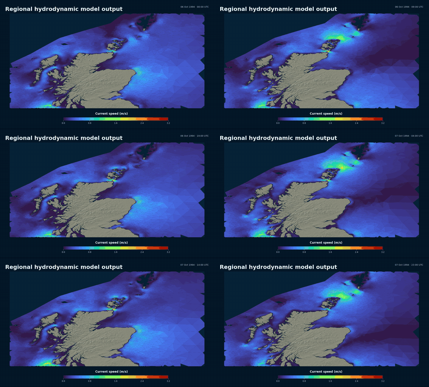
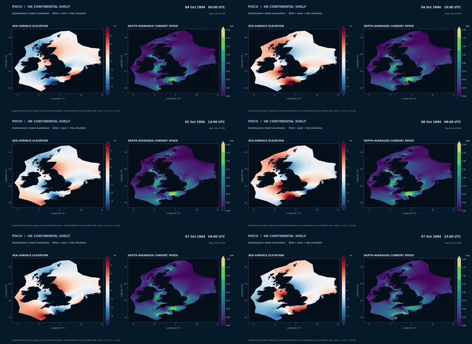
Animated results from a regional unstructured-mesh hydrodynamic model illustrate the evolution of tidal flows around northern Scotland and across the wider UK shelf. These are visualisations of computed model output, presented with consistent colour scales and coastal context.
Northern Scotland · Current-speed evolution
UK shelf · Regional tidal modelling
METOCEAN & DESIGN CONDITIONS
Directional and extreme environmental analysis.
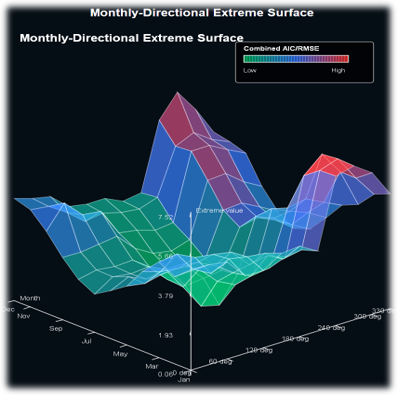
POCO Metocean supports statistical characterisation of environmental records, including operational and monthly or directional extremes to inform engineering design conditions.
Statistical modelling provides site-specific operational and extreme design conditions to inform structural and installation assessments.
SEABED MOBILITY · REPEAT BATHYMETRY
Understanding seabed change to inform NMRL assessment.
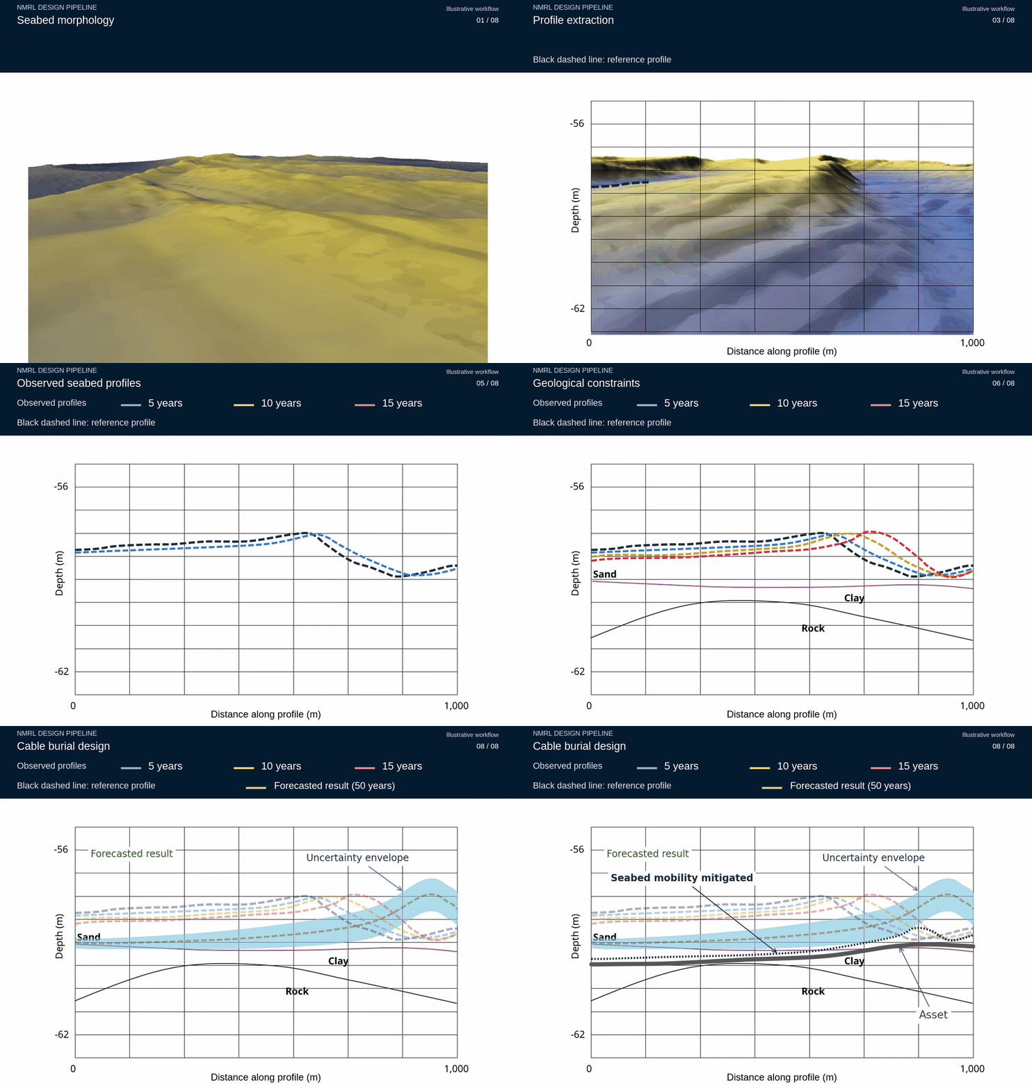
Research into mobile seabed morphology combines repeat multibeam bathymetric surveys, bedform displacement and dune-volume analysis with hydrodynamic and sediment-transport interpretation. The evidence supports site-specific assessment of erosion, deposition and seabed variability.
For offshore assets, these methods can inform statistical bed-level envelopes, NMRL assessment, cable burial requirements, exposure and free-span sensitivity over the design life.
Repeat multibeam survey research shows how observed bedform evolution can be analysed to inform statistical seabed mobility envelopes, NMRL assessment and subsea burial design.
ROCK PROTECTION · SUBSEA STABILITY
Rock protection and stabilisation assessment.
POCO Engineer supports stability and design assessments for rock berm protection, incorporating environmental loading, geometry, submerged weight and hydraulic response. Related SGP assessment scopes include rock placement, scour protection, cable and pipeline interaction, and the stability of rock bags or mattresses.
Rock protection assessments connect environmental loading with berm geometry, hydraulic stability, installation considerations and subsea asset performance.
DETAILED CFD · SUBSEA FLOW MODELLING
Flow around complex submerged structures.
SGP applies three-dimensional CFD to investigate local flow patterns, acceleration, recirculation and structure–flow interaction. The examples below illustrate modelling around complex submerged geometry and near-bed pipeline configurations.
Three-dimensional CFD reveals flow trajectories, near-structure interaction and wake patterns around complex submerged geometry, supporting the understanding of local hydrodynamic effects.
CFD DEMONSTRATION · ORIGINAL MODEL OUTPUT
Flow trajectories around detailed submerged geometry
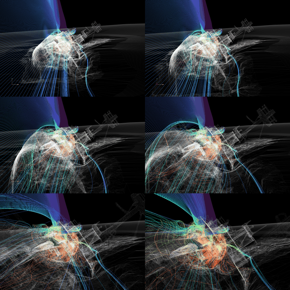
A clean technical sequence showing the structure's geometry, computed flow velocities and coherent flow features.
Animated CFD trajectories around detailed shipwreck geometry illustrate SGP's capability to examine flow behaviour around complex submerged structures.
LOCAL CFD · PIPE–BOUNDARY INTERACTION
Hydrodynamic flow interaction around a plate-mounted pipe.
This unsteady CFD visualisation illustrates a changing, colour-mapped solution around a cylindrical pipe mounted close to a flat boundary. The animation includes the local computational mesh and developing downstream flow structures.
A closer look at the pipe and near-boundary region helps communicate how detailed geometry and local numerical resolution are used to investigate offshore infrastructure.
The local computational mesh and evolving flow field illustrate how geometry-led modelling can support assessments of hydrodynamic loading and near-bed interaction for subsea pipelines.
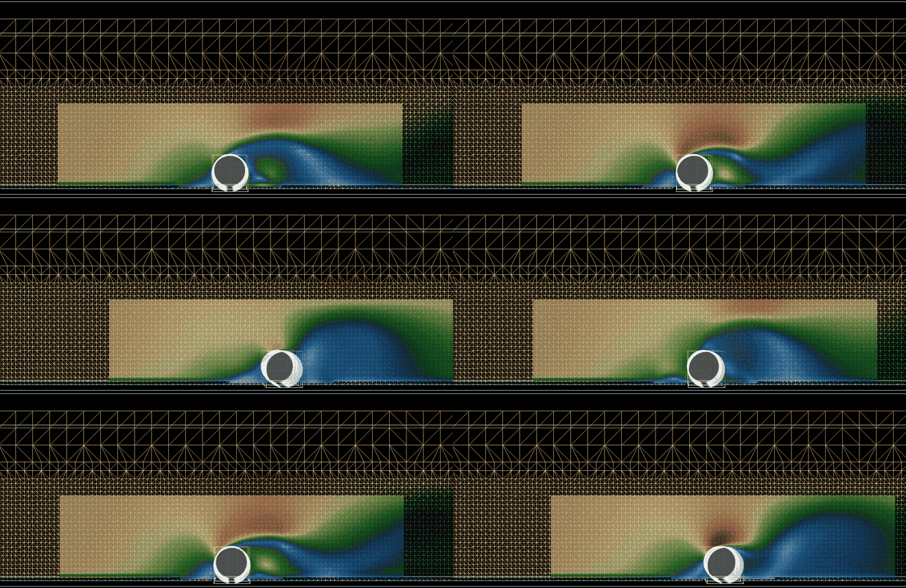
Animated CFD demonstration showing the computational mesh and changing downstream field around the pipe. Cropped to the region of interest; eight-second excerpt from the original simulation.
ENGINEERING EVIDENCE
Have an offshore engineering challenge to explore?
SGP can discuss suitable modelling approaches, the evidence required and how analysis could inform a particular design decision.
